


The small parts demand extreme precision in every single process step. Any invisible micro level defects can make entire batches completely useless. The tight tolerances require specialised techniques and equipment. Any minor deviations will produce parts that cannot be used. These challenges are almost never obvious during initial design.
The right injection molding dies manufacturers understand these unique inherent challenges. These issues do not appear during small initial test runs. They only become obvious once full volume production.
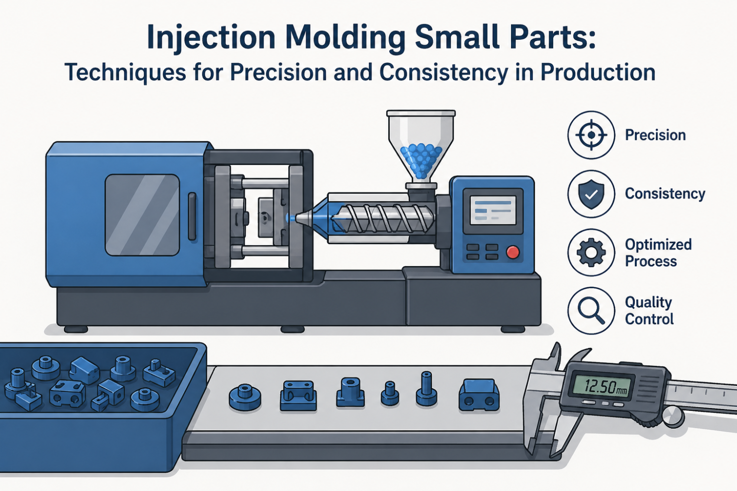
Advanced Techniques for Precision and Consistency in Production
Micro-Tooling Design for Tight Dimensional Control
The insert positioning must hold accuracy within 0.001 inches. There is no deviation from this standard that is acceptable for micro parts. The steel grades with minimal thermal expansion eliminate most drift. The tool steel hardness above 58 HRC prevents gradual wear over runs. The plastic molded products manufacturers will prioritise these factors over raw lead time.
The mirror finish surfaces reduce friction and part ejection drag. The core pin diameters are calculated to strict predefined deflection limits. Venting channels are sized to allow air escape without creating a flash.
The right injection molding dies manufacturers will verify every one of these values. The clients should never accept any deviation from these base design rules.
Shot Size Precision for Minimal Material Waste
The screw diameter is selected for consistent resin metering. The barrel heating zones must be held within 2 degree operating windows. Back pressure settings are tuned to create uniform melt density.
Final shot to shot weight variation must stay below 0.5 per cent. The cushion size is optimized for consistent repeatable pressure transfer. The injection speed ramps are used to prevent unwanted shear heating.
The reputable plastic die mold manufacturer teams will adjust these on the first run. These adjustments have almost no impact on stated cycle time. They will cut material waste by double digit percentages.
Gate Design Optimization for Small Cavity Filling
The gate cross sectional area ratios are set for balanced cavity flow. Pin gates under 0.5mm provide a clean and consistent break off after molding. The hot runner tip geometry is modified for consistent repeatable resin drops. The reputable injection mold manufacturers will provide full documentation for all values.
The gate freeze time is calculated individually for every part geometry. Flow length to thickness ratios are kept strictly under 150 to one. The shear rate limits are enforced to prevent permanent polymer degradation.
The plastic injection molds are designed around these exact gate parameters. Any small deviations will create visible and structural part defects. Most gate related issues are never identified during initial tool sampling. They will only appear once production runs reach ten thousand parts.
Wall Thickness Control in Thin Section Parts
The minimum wall thickness is set based on the specific material flow properties. The rib height ratios are limited to maintain long term structural integrity. The sink marks are prevented through a uniform and cross section design.
The draft angles are increased slightly for all walls by one millimetre. Corner radius sizing removes all common points of stress concentration. Undercuts are eliminated wherever possible to allow clean and consistent ejection.
Many experienced injection mold manufacturers will flag bad wall geometry early. Many designers will push for thinner walls without understanding the tradeoffs. A 0.1mm change can make a part completely impossible to mold. This is one of the most common sources of rejected production parts.
Cooling Channel Placement for Even Temperature Distribution
The conformal cooling is used for all parts with non-trivial complex geometry. The channel diameter is sized specifically to create a full turbulent water flow. The inlet and outlet water temperature differential is kept under ten degrees.
Total cycle time can be reduced by 30 per cent with a correct cooling design. Warpage is almost entirely eliminated through a fully symmetric cooling layout. The mold surface temperature variation is held within five degrees across all faces.
Many reliable custom plastic mold manufacturers will provide full cooling simulation reports. Most use standard straight cooling even when it is completely unsuitable. Bad cooling is the single largest cause of dimensional variation in production. This issue will never be fixed with any amount of process tuning later.
Ejection Force Management for Delicate Components
The ejector pin count and placement are set for even load distribution across the part. Pin diameter is sized to prevent permanent visible marking on the part surface. Stripper plates are used for very thin parts that cannot tolerate point loads.
Air blast systems are used for the most delicate and extremely thin wall components. Ejection speed is tightly controlled to prevent part deformation on removal. Return pin timing is adjusted to ensure a full and consistent reset every cycle.
The plastic molded products manufacturers will test the ejection force on the first shot. Most ejection related damage happens in the first three weeks of the production run. Small amounts of wear will gradually increase the force until parts start breaking.
Flash Control in Micro Geometry Features
Parting line design is the primary factor in minimal flash formation. The clamp force is calculated exactly to provide proper sealing at the interface. Wear plate maintenance schedules are defined for consistent long-term shutdown.
The vent depth is sized to allow gas escape. The specific surface finish requirements are applied directly at the parting line. The inspection methods ensure micro-level flash detection and measurement.
The good injection molding dies manufacturers will include these features as standard. A flash that measures less than one micron will still cause assembly issues. Most manufacturers will tell you this level of flash is unavoidable. Many high quality plastic injection molds will run half a million shots without flash.
Material Flow Dynamics in Narrow Channels
The melt temperature is optimised to provide exact and consistent viscosity control. The injection pressure profiles are adjusted for complete uniform cavity filling. The hold pressure duration is set for maximum long term dimensional stability.
The flow front advancement is monitored for every single shot in production. Weld line strength is tested and validated for all thin section parts. Molecular orientation effects are accounted for in all final design decisions.
An experienced plastic die mold manufacturer will tune these parameters over three days. Small adjustments here will create far larger improvements than any tool change.
The reliable custom plastic mold manufacturers will complete all of this work without prompting. Most will not mention these steps unless you ask for them.
Conclusion
There are no single big changes that will fix consistent bad results. Their consistency comes from systematic control of every process parameter. The quality systems must match the precision demanded by tiny geometries. Most existing quality checks are completely useless for this class of part. Every step from tool design to final packing needs equal attention from the injection molding dies manufacturers.
Small injection-moulded parts are the most difficult parts to manufacture. Any variations can go unnoticed on a large part to make a small part unusable. If you need reliable, high-precision small parts run after run, get in touch at (647) 294-5240 or email info@plasticinjection-molds.com for a detailed custom quote.